

1、 Overview of machine vision camera
The main function of the camera is to collect images. The earlier camera is called analog camera, which needs to be used with image acquisition card. The analog electrical signal is converted into digital electrical signal by the acquisition card, and then transmitted to the computer. With the development and popularization of digital interface technologies such as IEEE1394, GigE, USB 3.0, camera link. Coaexpress, analog cameras are gradually replaced by digital cameras. Digital cameras follow certain communication protocols and can directly convert the collected images into digital electrical signals, so it has become the mainstream camera in machine vision system.
1. CCD Sensor
Charge coupled device (CCD) is a kind of semiconductor imaging device, which can sense light and convert optical signal into electrical signal. It has the advantages of high sensitivity, strong light resistance, small size, long life and vibration resistance. The typical CCD camera is mainly composed of CCD chip, driving circuit, signal processing circuit, video output module, electronic interface circuit, optical mechanical interface, etc. The more the number of pixels contained in CCD chip, the higher the picture resolution.
2. Working principle of CCD camera
The light from one side of the object is focused on the CCD chip through the optical lens. Under the driving pulse provided by the driving circuit, the CCD completes the conversion, storage, transfer and reading of optical charge, so as to convert the optical signal into electrical signal output. The signal processing circuit receives the electrical signal from CCD, and carries out the pre-processing such as sample and hold, correlation double sampling, automatic gain control, and then synthesizes the video signal, which converts the electrical signal from CCD into the required video format.
3、 Composition and working principle of CMOS camera
1. CMOS Sensor
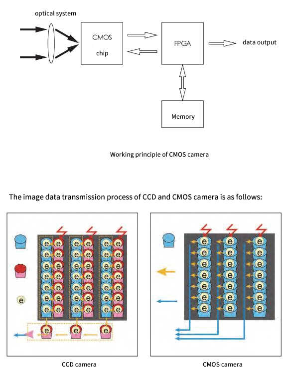
CMOS is the abbreviation of complementary metal oxide semiconductor (CMOS). CMOS technology integrates image sensor array, driving and control circuit, signal processing circuit, analog-to-digital converter, all digital interface circuit, etc., so as to improve the integration and design flexibility of CMOS camera. It is composed of peripheral circuit, DSP, CMOS module. The photosensitive chip converts the incident optical signal into electrical signal, collects and stores the charge signal in a certain form, and then outputs it to FPGA chip. FPGA preprocesses the signal and then caches it to memory for subsequent image transmission. The image is transmitted to the image receiving terminal through the corresponding communication interface.
2. The working principle of CMOS camera
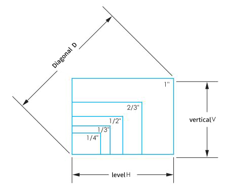
In the process of photoelectric conversion, the workflow of CMOS camera is similar to that of CCD camera, which uses photodiode for photoelectric conversion. The main difference between them is the way of image data transmission. In the CCD sensor, the charge data of each pixel in each row will be transmitted to the next row of pixels in turn, which is output by the bottom part, and then amplified by the amplifier at the edge of the sensor, so the signal output consistency is good; in the CMOS sensor, each pixel unit will be integrated with an amplifier and a / D conversion circuit, and the CMOS chip can directly output digital Most CMOS cameras are designed with FPGA or DSP processing module directly, which can pre process image data such as filtering and correction.

4、 Camera Classification
1. By Chip Process Type
| Classification | Main Differences |
| CMOS |
(1) CMOS is integrated on metal oxide semiconductor materials; (2) The manufacturing cost and power consumption of CMOS are low; (3) The color restoration ability is weak; (4) CMOS chip has rolling shutter type exposure and global exposure. Rolling shutter exposure is suitable for shooting still objects, and moving objects have dragging shadows and images will deform; global exposure can capture still or moving objects; |
| CCD |
(1) CCD is integrated on semiconductor single crystal material; (2) The cost and power consumption of CCD are high; (3) The color restoration is relatively strong, and the image sharpness and clarity are good; (4) The whole exposure mode or CCD exposure mode can be used; |
| Linear Array Camera |
(1) The chip is linear; (2) There must be relative motion between the camera and the object in order to image; (3) The price is relatively high; (4) It has very high row frequency and horizontal resolution; (5) Due to the large amount of data transmission, the data transmission interface is generally GigE interface, Cameralink interface and coaexpress interface. |
|
Array Camera |
(1) The chip is area array, and the camera interfaces are C, CS and F; (2) Objects can be imaged at rest or in motion; (3) Prices vary according to performance; (4) Two dimensional image information can be obtained in real time, and the image can be measured intuitively; data transmission interfaces include GigE, IEEE1394, USB, camera link and other interfaces. |
2. By Image Mode
|
Classification |
Main differences |
|
Color camera |
The image is in color |
|
Monochrome camera |
The image is grayscale |
3. According to the signal output mode
| Classification |
Main Differences |
| Analog Camera |
(1) Generally, the resolution is low, and the acquisition speed is slow. The typical frame rate is 30 frames per second, which is cheap;
(2) Analog cameras are divided into progressive scanning and interlaced scanning. Generally, they are interlaced scanning, and image transmission is vulnerable to noise interference, resulting in image quality degradation; (3) The output of the signal is analog signal, and the image acquisition card is used for analog / digital signal conversion outside the camera; (4) More used in real-time monitoring and other security industries, the market utilization rate is gradually reduced. |
| Digital Camera |
(1) The resolution ranges from 300000 to 120 million, with high acquisition speed and different prices;
(2) There are rolling shutter exposure and global exposure, the image quality is good; (3) The signal output is digital signal, and the A / D signal conversion is completed inside the camera; (4) Gradually replacing analog cameras. |
4. Other Classification Methods
|
By Resolution Size |
It can be divided into ordinary resolution camera and high resolution camera; |
|
According to the output signal speed |
It can be divided into ordinary speed camera and high speed camera; |
|
Spectral Response |
It can be divided into visible (ordinary) camera, infrared camera, ultraviolet camera, etc. |
5、 Main parameters and application of area array camera
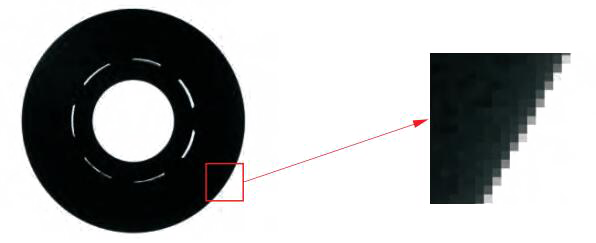
1. Sensor Size
That is, the target size is measured by the diagonal length of the chip; the linear array camera is measured by the transverse length of the chip. In industry, the commonly used sensor size of area array camera is shown in the table below, but the actual size is slightly different.
|
Chip |
Horizontal H (mm) |
Vertical V (mm) |
Diagonal D (mm) |
|
1" |
12.8 |
9.6 |
16.0 |
|
2/3" |
8.8 |
6.6 |
11.0 |
|
1/2” |
6.4 |
4.8 |
8.0 |
|
1/3" |
4.8 |
3.6 |
6.0 |
|
1/4" |
3.2 |
2.4 |
4.0 |
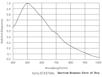
2. Pixels
Pixel is the smallest unit of image. As shown in the following figure, the original image is partially enlarged, each small cell represents a pixel, and each pixel corresponds to a gray value.

3. Pixel
Pixel is the smallest photosensitive unit on the camera chip, and each pixel corresponds to a pixel in the image.
Pixel size is the actual physical size of each pixel on the camera chip. The common physical sizes are 2.2um, 3.45um, 3.75um, 4.8um, 5.5um, 5.86um, 7.4um, etc. For a chip of the same size, the larger the pixel size, the more photons can be received, the higher the sensitivity and sensitivity of the chip, and the brighter the image will be.
5. Pixel Depth
The number of bits of data used to store each pixel is called pixel depth. For black and white cameras, pixel depth defines the gray scale from dark to bright. For example, if the pixel depth is 8 bits, the output image gray level is 2 to the eighth power, that is, o-255 is 256 levels in total. When the pixel depth is 10 bits, the output image gray level is the 10th power of 2, that is, o-1023 is 1024 levels in total. The larger the pixel depth, the higher the accuracy of measurement, but also reduce the speed of the system. Generally, 8-bit pixel depth is used in industry.
6. Resolution
The resolution is determined by the number of pixels arranged on the chip array. For the area array camera, the resolution is determined by multiplying the number of horizontal pixels and vertical pixels. For example, the resolution of a camera is 1280 (H) × 1024 (V), which means that the number of pixels per line is 1280. There are 1024 lines of pixels. The resolution of this camera is about 1.3 million pixels. When imaging the same field of view, the higher the resolution, the more obvious the display of details. At present, the resolution of commonly used cameras is 300000, 1300000, 2000000, 50000000, 10million, 29000000, 71000000, 120m, etc.


7. Accuracy
The actual physical size of each pixel in the image.
Accuracy = Field of view in one direction / Resolution of camera in one direction
For example, if the length of the horizontal direction of the field of view is 32mm and the horizontal resolution of the camera is 1600, the accuracy of the vision system can be obtained as 0.02mm per pixel. In practical application, in order to improve the stability of the system, the theoretical accuracy of machine vision is usually higher than the required accuracy.
8. Frame Rate / Line Frequency
The acquisition frequency of the camera is represented by frame rate for area array camera and row frequency for linear array camera. The unit of frame rate of area array camera is FPS (frame per second), that is, frames per second. It refers to how many images the camera can collect per second, and one image is one frame. For example, 15 frames per second means that the camera can capture up to 15 images per second. Generally speaking, the higher the resolution, the lower the frame rate. The line frequency unit of linear array camera is Hz, and 1 Hz corresponds to the acquisition of a row of images. For example, 50 kHz / s means that the camera scans 50000 lines in 1 second. Generally speaking, the higher the resolution, the lower the line frequency.
9. Gain
The amplification ratio of input signal and output signal is used to improve the brightness of the picture as a whole. The unit of gain is dB.
10. External Trigger
Industrial cameras generally have the function of external trigger, which can control the image acquisition according to the external signal, that is, to receive an external signal and collect an image. In practical use, the external trigger function of sensor and camera can be used flexibly.
*Note: in some occasions where the external trigger function of the camera is used, other electronic equipment may be used, such as DC / AC motor, frequency converter, contactor, etc. if the shielding of various signals is not good, it is likely to cause interference to the external trigger signal of the camera and affect the use of the camera.
*Signal output: when using the external trigger function of the camera, generally speaking, the lighting of the external light source is also in the external trigger state with the camera. The light source is on when the camera is collecting, but it is off when the camera is not collecting. Some cameras have the function of signal output, output trigger signal, control the light source on and off, so as to cooperate with the camera image acquisition.
11. Exposure Time / Exposure Mode
Exposure time refers to the time when light is projected onto the sensor chip of the camera. Generally, the longer the exposure time, the brighter the image. External trigger synchronous acquisition mode, the exposure time can be consistent with the line period, or a fixed time can be set. The exposure methods of industrial camera are divided into line exposure and frame exposure, in which line exposure refers to line by line exposure, and frame exposure is one-time exposure of all pixels. Linear array camera is line by line exposure, and fixed line frequency can be selected.
12. Drag
When shooting a moving object, the exposure time does not match with the moving speed, resulting in repeated imaging of the object on the pixel.


14. Noise / SNR
-400nm)。 Different spectral response cameras are selected according to different applications.
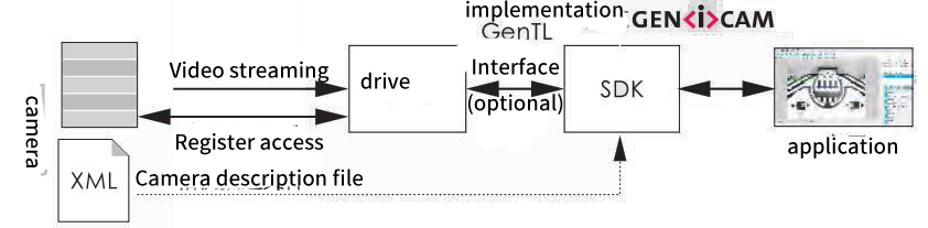
Genlcam (camera general protocol) can provide universal programming interface for various types of cameras, so as to realize the interchangeability of different brands of cameras. Its purpose is to realize the same application programming interface (APL) in the whole industry.

Mr. Su:13912634161