

Imaging principle of lens
Lens imaging is based on the principle of convex lens imaging. Through the combination of lenses, the light emitted or reflected by the object is imaged on the image plane (coincident with the chip plane). The combination of concave convex lens can effectively balance spherical aberration, off-axis aberration, chromatic aberration and other aberrations, and improve the imaging quality.


Introduction of technical indicators
● Focus / Focal length
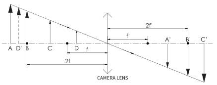
When the light parallel to the optical axis shoots into a convex lens, the ideal lens should be that all the light rays gather at a point and then spread out in a cone shape. The point where all the light rays gather is called the focus.
For a single lens, the focal length refers to the distance from the optical center to the focus, as shown in Fig. 1; for a lens group composed of multiple lenses, the focal length refers to the distance from the main plane of the image to the focus, as shown in Fig. 2.


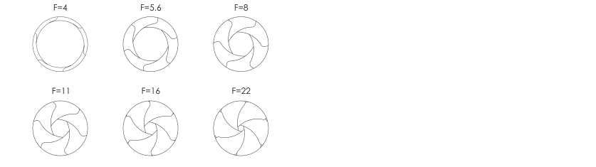
● Aperture
Inside the lens, there is a polygonal or circular aperture grating device with variable area. This device is called an aperture. The function of aperture is to control the luminous flux of the lens. The aperture coefficient is usually used to describe its size. The aperture coefficient refers to the ratio of the focal length f 'to the diameter D of the whole lens entrance pupil, which is usually expressed by F / #. The calculation formula is: F / 0 = f '/ d.


The smaller the F / 0 value, the larger the aperture. Generally, the F / 0 value is increased by 2 times, so the commonly used counting of aperture is f1.4, f2.0, f2.8, F4. O In the same unit time, the luminous area of the upper stage is twice that of the next stage. For example, if the aperture is adjusted from F / 8 to f / 5.6, the luminous area will be doubled.

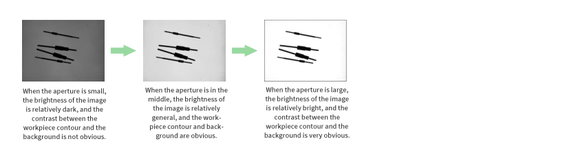
The influence of aperture on image brightness: under the same application conditions, the larger the aperture, the brighter the picture.

Working distance: when the lens is focused clearly, the distance from the measured target to the front of the lens is called the working distance. In practical application, the lens can not focus the target at any object distance at the same time, so the working distance of the lens has a certain range.
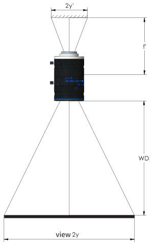

FOV / FOV
● Field of view angle
In optical engineering, the field of view angle refers to the opening angle of the lens to the image sensor, that is, if y 'is the half diagonal length of the sensor, the field angle is 20 ~ 2 * arctan (y' / F ').


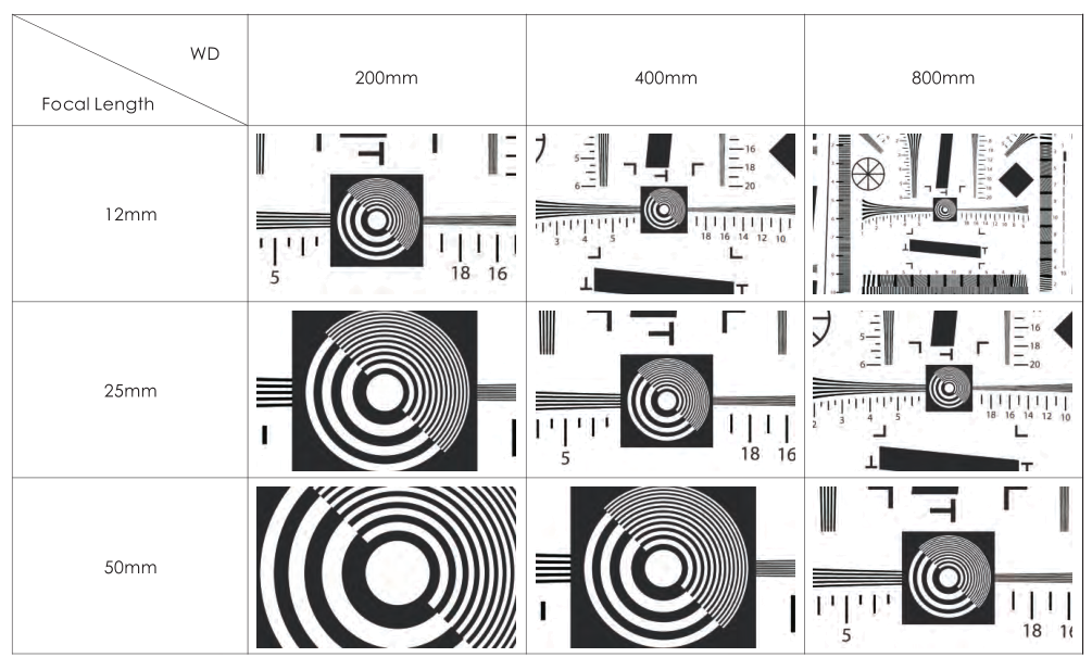
Under the same working distance, the shorter the focal length is, the larger the field of view is, and the larger the field of view is; under the same focal length, the field of view is fixed, and the farther the working distance is, the greater the field of vision is.

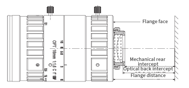
Rear Intercept
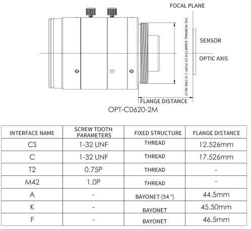
●Flange distance: the distance between lens flange surface and image plane (chip).
●Mechanical back intercept: the distance from the last mechanical surface of the lens to the image plane.
●Optical back intercept: the distance from the vertex of the lens surface at the last end of the lens to the image plane.

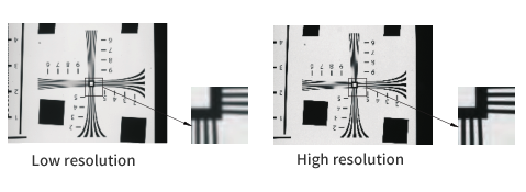
Resolving Power
Resolution refers to the minimum resolvable feature size of the measured object that can be measured by the optical system. The smaller the detail that the lens can distinguish objects, the higher the resolution of the lens. The image can be described as logarithmic (IP) per side. In practical application, it is suggested that the resolution of lens should not be lower than that of camera.

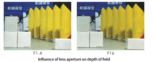
Depth of Field
Depth of field: the depth of object space in which a clear image can be obtained on the image plane. That is: in a certain range before and after the object plane (focus), the image is still clear without focusing. The depth of the clear imaging space is the depth of field.


Main factors affecting depth of field
The larger the aperture, the smaller the depth of field; the smaller the aperture, the greater the depth of field.
The longer the focal length of the lens, the smaller the depth of field; the shorter the focal length, the greater the depth of field.
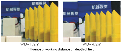
The farther the shooting distance, the greater the depth of field; the closer the distance, the smaller the depth of field.

The two pictures above were taken with the same aperture and the same working distance. The left picture was taken with opt-c1216-5m, with the focal length of F '= 12mm; the right picture was taken with opt-c3514-5m, with the focal length of F' = 35mm. It can be seen that the depth of field in the left picture is larger than that in the right picture.

● Magnification
Magnification is defined as the ratio of the size of the image to the size of the object. -When 1 < β < 0, the opposite side of the object image becomes an inverted and reduced real image, as shown in AA ', which is the imaging principle of the lens.
=-At 1:1, the opposite side of the image becomes a solid image of inverted size, as shown in BB '. When < - 1, the object image is on the opposite side and becomes a real image with inverted magnification, as shown in CC ', which is the imaging principle of microscope. β> When o, the object image is on the same side, forming a virtual image of upright magnification, as shown in DD ', which is the imaging principle of the magnifying glass.

Optical Distortion
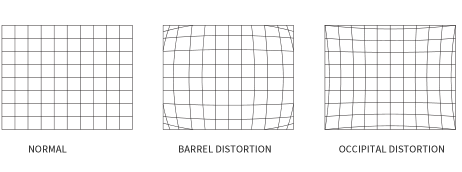
Optical distortion: due to the different magnification of lens in different field of view, the image loses the similarity with the object. This kind of image deformation defect is called optical distortion. Optical distortion only affects the geometry of the image, but does not affect the clarity of the image. There are two main types of optical distortion, barrel distortion and pillow distortion (as shown in the figure).

TV Distortion
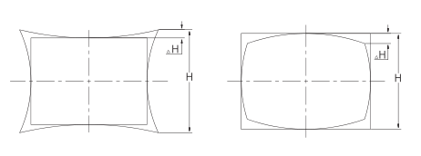
TV distortion is a measure of image visual distortion, and there are many definitions of TV distortion. The calculation formula of riaatv distortion is as follows:
Tv.Distortion (%)=×100%

Lens Classification
There are many ways to classify lenses:
Classification by function: fixed focus lens, zoom lens and fixed aperture lens;
Classification by use: telecentric lens, FA lens, linear scan lens, macro lens (or micro lens);
Classification by perspective: ordinary lens, wide-angle lens and telephoto lens;
Classification by focal length: short focal length lens, medium focal length lens and long focal length lens.
In industrial applications, the most commonly used lenses are focus lens and telecentric lens. Fixed focus lens refers to the lens with fixed focal length; Telecentric lens is a lens specially designed to correct the parallax of traditional lens. In a certain working distance range, the magnification of the image obtained does not change with the change of working distance, that is, the image size of the object under measurement is the same under different working distance, so it is widely used in high-precision measurement. Generally, it can be divided into the following categories:
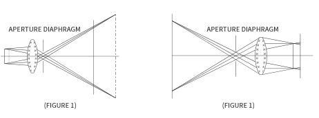
Telecentric lens: the main light of the object side is parallel to the optical axis, that is, the convergence center of the main light is located at the infinite distance of the object side, which can eliminate the reading error caused by inaccurate focusing. (Figure 1)
Image telecentric lens: the main ray of the image side is parallel to the optical axis, that is, the convergence center of the main light is located at the infinite distance of the image side, which can effectively eliminate the measurement error caused by the inaccurate focusing of the image side. (Fig. 2)


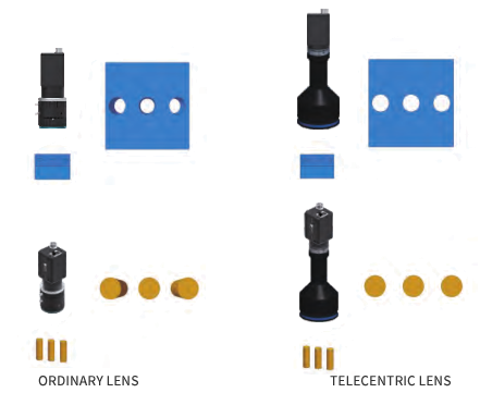
When the system accuracy is not required by conventional surface defect inspection and judgment, ordinary lens can be selected. For the application requirements of precision measurement, telecentric lens should be selected, because when imaging with ordinary lens, due to different working distance, the magnification is inconsistent, resulting in parallax, that is to say, the effect of near large and far small will be produced, which will affect the measurement accuracy. Telecentric lens can ensure the same magnification in a certain range, overcome parallax, and improve the measurement accuracy. The picture below shows the comparison between the ordinary lens and the telecentric lens

Lens Selection
Selection Ideas
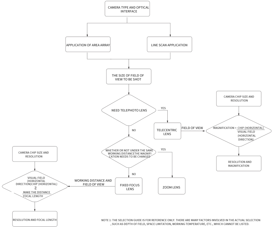
In machine vision system, the main function of lens is to image the workpiece onto the camera sensor chip, so the selection of lens will directly affect the overall performance of machine vision system. Generally, the lens can be selected reasonably in the following ways:

● Key Points
A. Focusing ring and optical interface
The structural component that adjusts the relative position of the lens group or the rear focal length of the optical system to make the imaging clear is called the focusing ring (or focusing ring). The following figure shows the imaging effect of the focal ring in different states:


The mechanical interface between the lens and the camera. The common optical interface in the industry has formed a general specification, such as C port, CS port, f port and K port.

B. Maximum compatible camera chip size
The maximum range of clear lens that the camera can support. In the actual selection of camera and lens, it should be noted that the maximum compatible chip size of the selected lens should be greater than or equal to the size of the selected camera chip.
The following is a description of the compatibility of common lenses and camera chips


Selection Process
A. First determine the application requirements (field of view, accuracy, mounting height, etc.).
B. The key optical performance parameters are calculated according to the application requirements. For example, the focal length can be calculated from the field of view, the working distance of camera field (horizontal direction), chip size and working distance: the focal length of chip (horizontal direction)
C. Resolution matching: in practical application, the resolution of lens should not be lower than that of camera.
D. The depth of field is required to be as small as possible due to the requirements of the actual depth of field.
E. Pay attention to the matching with the light source and select the appropriate lens.
F. Pay attention to consider the installable space of the usage environment.
Case Study:
Application requirements: the field of vision is 180mm × 135mm, the camera chip is 1 "(chip size is 12.8mm × 9.6mm), pixel size is 3.5um, camera interface is C-type interface, and
The working distance is less than 800mm.
(1) According to the formula of focal length, we can get: F '= working distance × (horizontal field of view △ chip) = 800 × (180  ̄ 12.8) = 56.89mm.
(2) Select the closest focal length, f 'is taken as 50 mm, and calculate the new working distance according to the determined focal length. The new working distance ~ (horizontal field of view + chip) × focal length = (180  ̄ 12.8) × 50 = 703.125mm, new working distance < 800mm, so the selected focal length is feasible.
(3) Pixel matching: pixel = 12.8 × (3.5 × 10) × 9.6 × (3.5 × 10) = 1.00 × 10⁷. It is recommended to select high-definition 10 million pixel fixed focus lens.
(4) Determine the interface as C interface.
(5) To sum up, opt-c5024-10m of OPT machine vision can be selected.


Mr. Su:13912634161